China Custom Steel Walkway Floor Grating Manufacturer
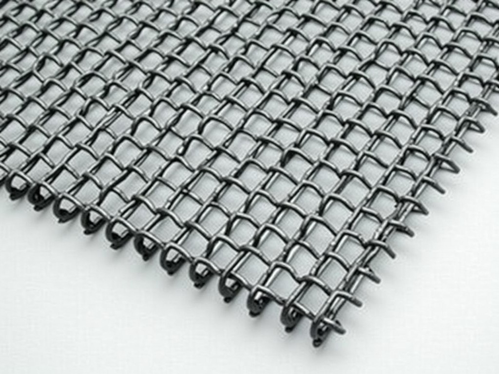
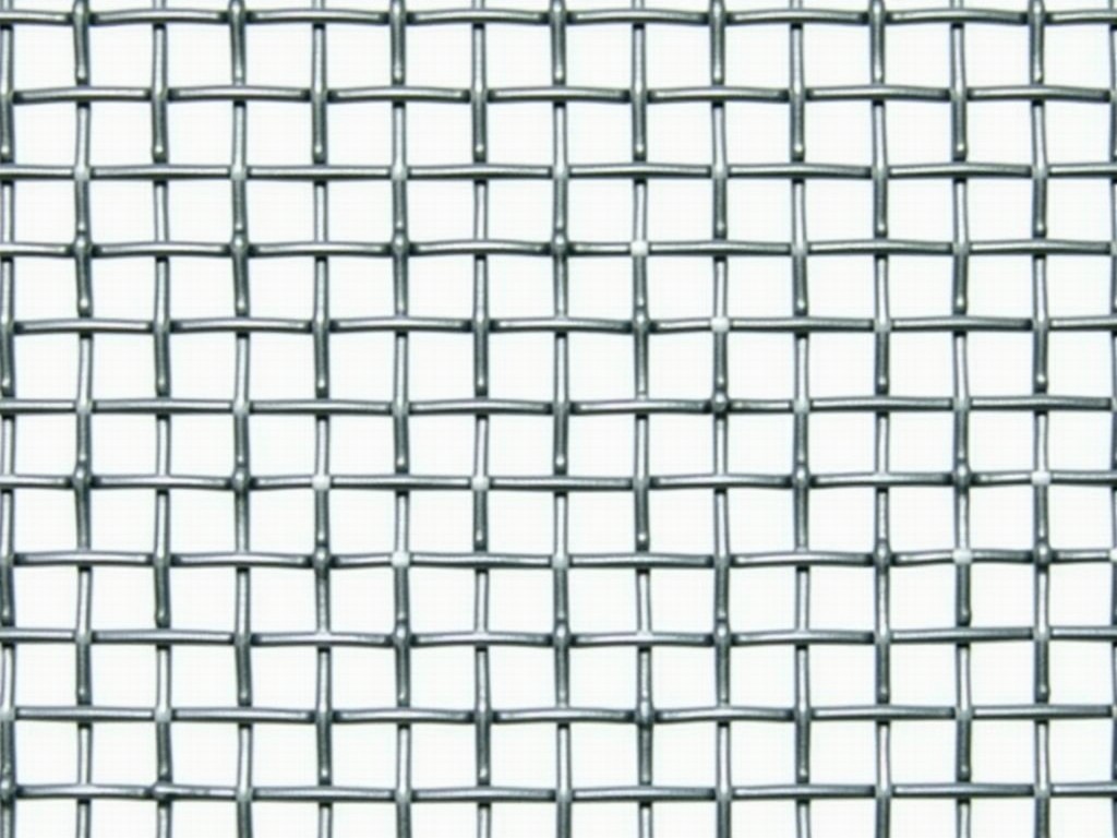
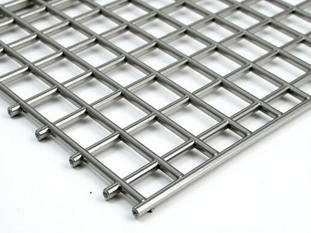
Steel walkway floor grating is a load‑bearing panel formed by parallel bearing bars joined at regular intervals with transverse cross rods. The open‑grid design provides slip resistance, drainage,
Request a QuoteChina Custom Steel Walkway Floor Grating Manufacturer
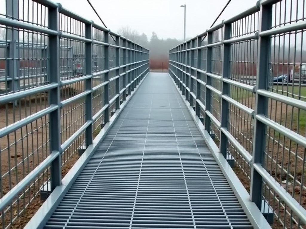
Steel walkway floor grating is a load‑bearing panel formed by parallel bearing bars joined at regular intervals with transverse cross rods. The open‑grid design provides slip resistance, drainage, and a lightweight yet stiff walking surface for pedestrian traffic in industrial plants, refineries, power stations, and commercial facilities.
Material Selection and Grades
Material choice directly influences mechanical strength, corrosion resistance, and fabrication cost. Common options include carbon steel grades Q235 and Q345 for general structural use, and stainless steel grades 304 or 316 where exposure to chemicals, salts, or moisture is expected. Hot‑dip galvanizing, powder coating, or epoxy paint can be applied to carbon steel to achieve a zinc coating thickness typically ranging from 55 to 85 µm, extending service life in outdoor or humid environments.
Load Bearing Capacity and Structural Design
Load capacity is determined by bearing bar size, bar spacing, support span, and the type of surface treatment. For a typical configuration of 25 mm × 5 mm bearing bars spaced at 30 mm, the grating can sustain a uniformly distributed load of approximately 5 kN/m² with a deflection limit of L/200 over a 600 mm support spacing. Increasing bar thickness to 8 mm or reducing spacing to 20 mm raises the capacity proportionally, allowing designers to meet specific live‑load or impact‑load requirements.
Customization Options
- Overall panel length and width, cut to fit irregular openings or equipment footprints.
- Bearing bar dimensions (height × thickness) ranging from 20 mm × 4 mm to 40 mm × 10 mm.
- Bar spacing (center‑to‑center) adjustable between 20 mm and 50 mm to balance open area and stiffness.
- Cross rod size and material, typically 6 mm × 6 mm carbon steel or stainless steel.
- Surface treatment: hot‑dip galvanizing, powder coating, epoxy paint, or left bare for indoor use.
- Edge finishing options such as welded edge bars, nosing plates, or stair treads with integral risers.
- Cut‑outs for pipes, conduits, or equipment mounts, reinforced with additional bearing bars.
Manufacturing Process
The manufacturing process typically begins with shearing or laser cutting of bearing bar stock to the required length. Slots or holes are punched or drilled at the prescribed spacing to receive the cross rods. Cross rods are inserted and secured either by resistance welding, pressure locking, or mechanical swaging, creating a rigid grid. After assembly, the grating undergoes cleaning, pre‑heating, and immersion in a molten zinc bath for hot‑dip galvanizing, followed by cooling and inspection. Alternative finishes such as powder coating are applied in a separate curing line after surface preparation.
Quality Control and Testing
Quality assurance follows a multi‑stage approach. Dimensional verification checks bearing bar height, thickness, and spacing against tolerance bands (typically ±0.5 mm for bar dimensions and ±2 mm for overall panel size). Weld integrity is assessed by visual inspection and, where required, tensile shear tests on sample couplings. For galvanized products, coating thickness is measured with a magnetic gauge to confirm compliance with the specified micron range. Load testing on representative samples validates that deflection remains within the L/200 limit under the design load, and any deviations trigger process adjustments before batch release.
Applications in Industry
Industrial facilities select this grating because it combines slip resistance with efficient drainage, reducing standing water and chemical accumulation on walkways. The open grid permits easy passage of small debris and facilitates cleaning, while the high strength‑to‑weight ratio simplifies handling and installation compared with solid plate flooring. In environments such as chemical processing plants, offshore platforms, and power generation stations, the grating’s resistance to corrosion (when galvanized or stainless) ensures long service life with minimal maintenance.
Typical Specifications
| Parameter | Typical Value / Customizable Range |
|---|---|
| Bearing bar size (height × thickness) | 25 mm × 5 mm (adjustable 20‑40 mm × 4‑10 mm) |
| Bar spacing (center‑to‑center) | 30 mm (adjustable 20‑50 mm) |
| Cross rod size | 6 mm × 6 mm (carbon steel or stainless) |
| Overall thickness | 25 mm (varies with bar size) |
| Surface treatment | Hot‑dip galvanizing (average Zn coating 60 µm) or powder coating; optional stainless steel bare |
| Uniformly distributed load capacity | ≈5 kN/m² (configurable per design) |
| Deflection limit | L/200 (standard) |
| Standard panel length | Up to 6000 mm (custom lengths available) |
Frequently Asked Questions
Can dimensions be customized? Yes. Panel length, width, bearing bar dimensions, and spacing are all tailored to the project layout and load requirements.
What information is needed before quotation? Required details include the intended clear span, expected live load, preferred material (carbon steel, stainless, galvanized), any required cut‑outs or edge finishes, and the desired surface treatment.
What materials are available? Carbon steel grades Q235/Q345, stainless steel 304/316, and optional alloy steel for high‑temperature applications.
How is quality inspected? Dimensional checks, weld shear tests, coating thickness measurement, and load validation on samples are performed per internal QA procedures and relevant standards.
What packaging methods are available? Gratings are bundled with steel straps, placed on pallets, and protected with corrosion‑inhibiting wrap; custom crating can be arranged for overseas shipments.
How are export shipments protected? Each bundle is wrapped in UV‑stable polyethylene film, corner protectors are added, and the pallet is secured with heat‑treated lumber to meet ISPM‑15 requirements.
What is the typical production lead time? Lead time varies with complexity but generally ranges from 2 to 4 weeks after drawing approval, with expedited options available.
How are samples arranged? Sample sections (typically 300 mm × 300 mm) can be provided upon request; shipping costs are usually borne by the requester.
Contact for Inquiry
To discuss your project requirements, request a quotation, or obtain technical drawings, please contact our engineering team. Provide the layout dimensions, load expectations, and any special finishes, and we will respond with a detailed proposal and lead‑time estimate.