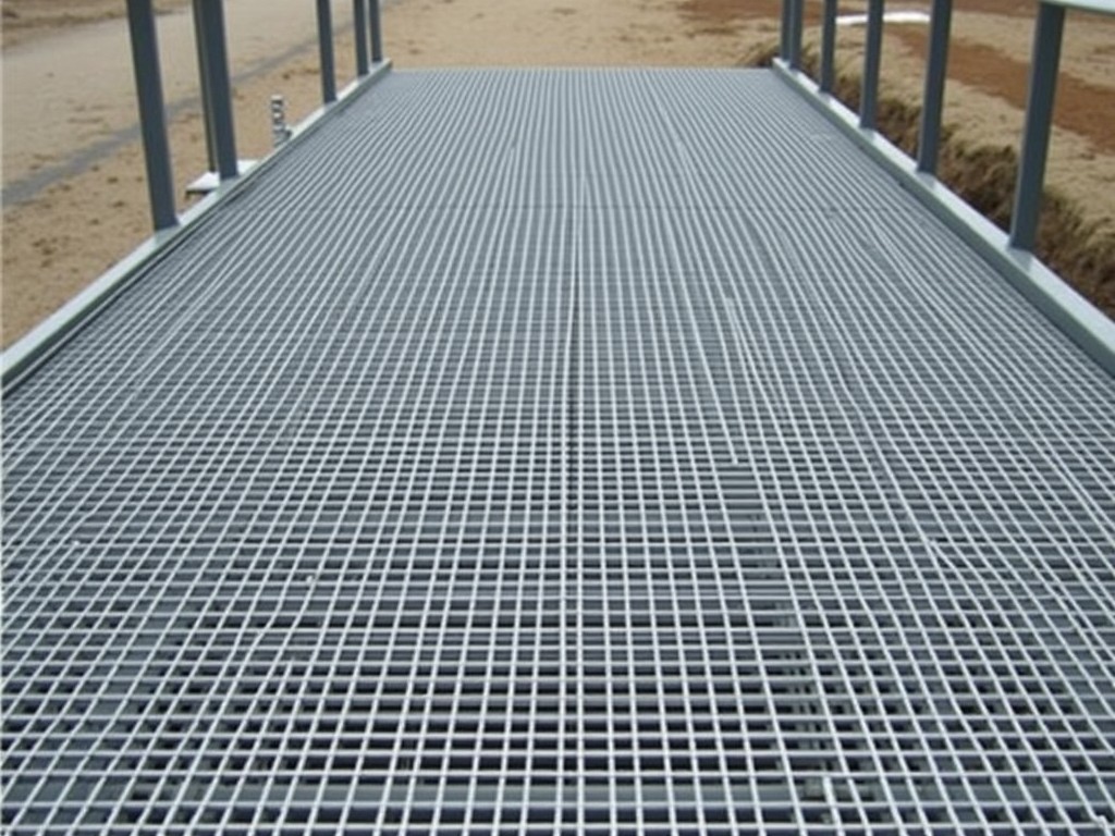
China Catwalk Steel Grating Walkway Manufacturer
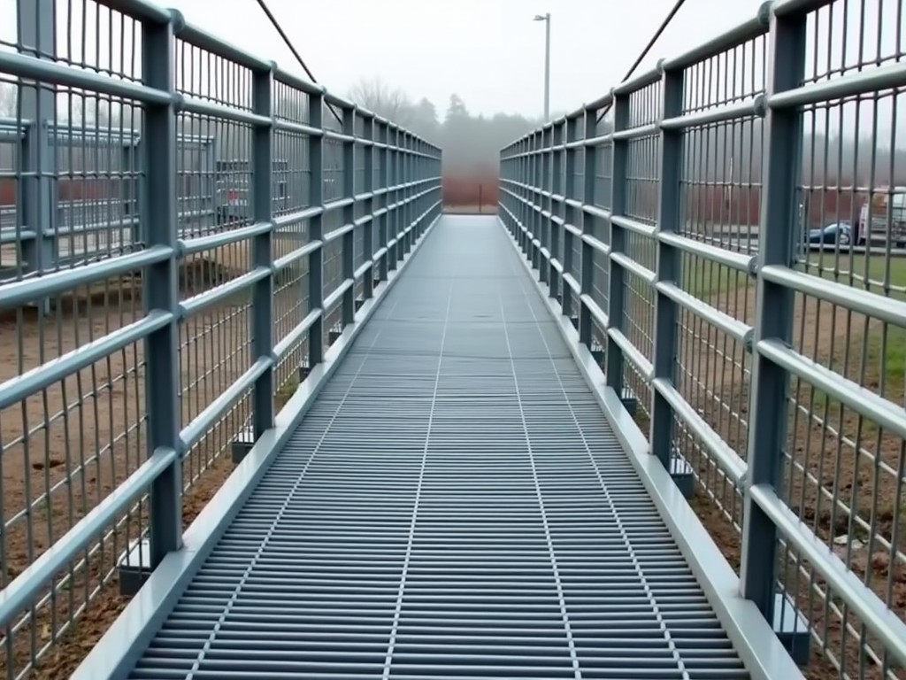
Catwalk steel grating walkways are fabricated load‑bearing panels designed to provide safe pedestrian passage over equipment, trenches, or uneven surfaces in industrial plants. They consist of
Request a QuoteChina Catwalk Steel Grating Walkway Manufacturer
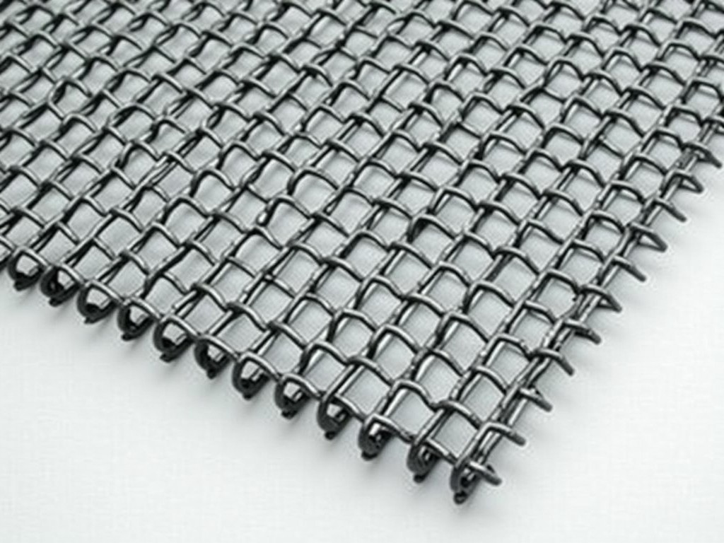
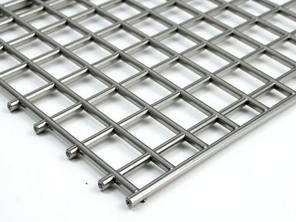
Catwalk steel grating walkways are fabricated load‑bearing panels designed to provide safe pedestrian passage over equipment, trenches, or uneven surfaces in industrial plants. They consist of bearing bars welded or pressure‑locked to cross rods, forming an open‑grid pattern that allows drainage, ventilation, and light transmission while supporting specified loads.
Load‑Bearing and Deflection Characteristics
Typical designs are calculated to sustain a uniform live load of 4 kN/m² with a maximum deflection not exceeding span/200 under service conditions. The bearing bar size, spacing, and material grade determine the section modulus, which is verified against the required moment capacity using standard steel design formulas.
Material Selection and Corrosion Protection
Carbon steel grades such as Q235 or Q345 are commonly selected for their yield strength and weldability. For environments with moisture or chemical exposure, hot‑dip galvanizing provides a zinc coating thickness of 55–85 µm, while stainless steel grades 304 or 316 offer inherent corrosion resistance without additional coating.
Industrial Applications and Functional Benefits
In petrochemical plants, catwalk gratings are installed above piping racks to allow inspection and maintenance without interfering with flow. The open area ratio, typically 65‑75 %, permits liquids and gases to drain freely, reducing slip hazards and preventing accumulation of debris. In power generation facilities, the gratings support walkways over turbine foundations where vibration resistance and fatigue performance are critical.
Standard Sizes and Customization Parameters
Standard panel widths range from 300 mm to 600 mm, with lengths up to 6 m limited by handling and transportation constraints. Bearing bar heights are offered in 25 mm, 32 mm, and 40 mm options, while bar thicknesses vary from 3 mm to 6 mm. Cross rod spacing is usually 30 mm or 40 mm, and the open area can be adjusted by altering the bar‑to‑space ratio to meet specific drainage or load requirements.
Quality Control and Testing Procedures
Each batch undergoes visual inspection for weld conformity and surface finish. Dimensional checks verify bar spacing, panel squareness, and length tolerances within ±2 mm. Mechanical properties are confirmed via mill test certificates, and galvanized coatings are measured with a magnetic thickness gauge to ensure compliance with the specified micron range.
| Parameter | Typical Value | Notes |
|---|---|---|
| Bearing bar height | 25 mm – 40 mm | Selected based on load span |
| Bearing bar thickness | 3 mm – 6 mm | Affects section modulus |
| Bar spacing (center‑to‑center) | 30 mm or 40 mm | Determines open area |
| Open area ratio | 65 % – 75 % | Influences drainage and weight |
| Uniform load capacity | Up to 5 kN/m² | Deflection ≤ span/200 |
| Surface treatment | Hot‑dip galvanized (55‑85 µm) or SS304/316 | Corrosion protection method |
Frequently Asked Questions
Common inquiries from engineers and procurement managers are addressed below.
- Can dimensions be customized? Yes, panel width, length, bearing bar size, and spacing can be adjusted to match project layout and load specifications.
- What information is required for a quotation? Required data include clear span, expected load, environmental conditions, preferred material, and any applicable standards (e.g., ANSI/NAAMM MBG 531).
- Which materials are available? Carbon steel (Q235/Q345), hot‑dip galvanized carbon steel, and stainless steel grades 304 and 316.
- How is quality inspected? Visual weld inspection, dimensional verification, coating thickness measurement, and review of material test certificates.
- What packaging methods are used for export? Panels are stacked on pallets, protected with edge guards, and wrapped in waterproof shrink film or placed in wooden crates depending on destination.
- What is the typical production lead time? Lead time ranges from 2 to 4 weeks after drawing approval, depending on order volume and material availability.