B2B Security Fencing Wire Mesh Supplier
Security fencing wire mesh functions as a engineered barrier that deters unauthorized crossing while maintaining visibility and structural continuity. Its performance is defined by the interaction of
Request a QuoteB2B Security Fencing Wire Mesh
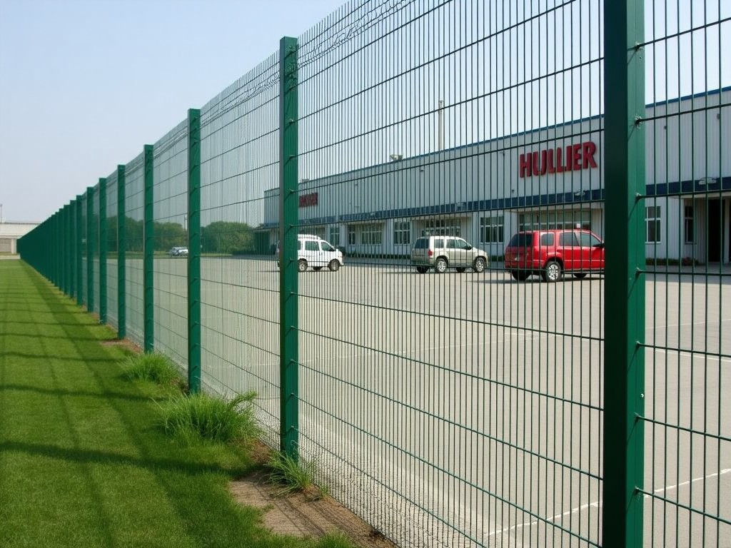
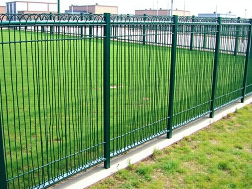
Security fencing wire mesh functions as a engineered barrier that deters unauthorized crossing while maintaining visibility and structural continuity. Its performance is defined by the interaction of material properties, aperture geometry, and installation method. Selection begins with an assessment of threat level, environmental exposure, and required service life.
Material selection begins with the base steel grade. Low‑carbon steel offers good formability and weldability, while high‑tensile steel provides higher yield strength for impact resistance. Stainless steel grades are chosen when chloride exposure or aesthetic longevity is critical. Coatings such as hot‑dip galvanizing (typically 55‑85 µm Zn), Galfan (Zn‑Al alloy), PVC overlay, or powder paint are applied to achieve corrosion resistance measured in grams per square meter of zinc equivalent.
Mechanical performance is quantified through tensile and yield tests on wire specimens. Typical tensile strength for galvanized low‑carbon wire ranges from 350 MPa to 550 MPa, with yield strength between 250 MPa and 400 MPa. Elongation at break usually falls between 10 % and 20 %, indicating sufficient ductility to absorb impact without brittle fracture. These values influence the mesh’s ability to resist cutting tools and dynamic loads from vehicular impact.
Aperture geometry and wire diameter directly influence climb and cut resistance. Common opening sizes vary from 25 mm × 25 mm to 100 mm × 100 mm square, while wire diameters are offered from 2.0 mm to 4.0 mm. Smaller apertures and larger wire diameters increase the difficulty of hand‑hold formation and reduce the effective cutting edge of bolt cutters. Designers often reference ISO 1461 for coating thickness and EN 10223‑3 for welded mesh dimensions when establishing baseline specifications.
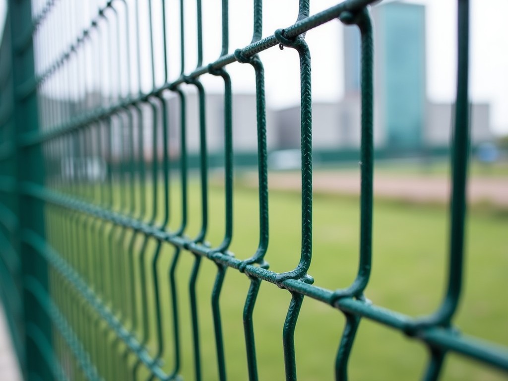
Manufacturing method determines the mesh’s structural behavior. Electric resistance welding at each intersection creates a rigid grid with uniform load distribution, suitable for high‑impact scenarios. Woven (knuckle or twist) meshes provide flexibility to follow uneven terrain and are easier to repair in situ. Panels are typically supplied in flat sheets or rolled form, with edge finishes such as folded selvages or trimmed ends to facilitate fastening.
Typical specification ranges are summarized below:
| Parameter | Typical Range | Notes |
|---|---|---|
| Wire diameter (mm) | 2.0 – 4.0 | Selected based on cut resistance |
| Opening size (mm) | 25 – 100 (square) | Aperture influences climb resistance |
| Tensile strength (MPa) | 350 – 550 | Wire grade dependent |
| Coating weight (gsm) | 60 – 120 | Equivalent zinc mass per m² |
| Roll width (m) | 1.0 – 3.0 | Standard widths; custom slitting available |
| Roll length (m) | 20 – 100 | Dependent on wire diameter and coil weight |
Application environments dictate additional performance criteria beyond basic strength. Utility substations require mesh that is electromagnetically transparent to avoid interference with grounding systems while providing anti‑climb protection. Highway median barriers demand high impact energy absorption and resistance to snow‑plow scraping. Correctional facilities prioritize anti‑cut properties, limited foothold geometry, and clear visibility for surveillance. Data centers often specify low‑radar‑cross‑section finishes and non‑conductive coatings to mitigate electromagnetic interference risks.
Customization aligns the mesh with site‑specific constraints and threat profiles. Options include selecting coating type (galvanized, Galfan, PVC, powder) to match corrosion expectations, adjusting panel height and width to match post spacing, integrating pre‑drilled holes or brackets for rapid attachment, and adding anti‑climb toppings such as razor wire, spikes, or rotating barriers. Surface color can be tailored for camouflage, aesthetic integration, or UV stability, while grounding lugs or conductive strips can be embedded for equipotential bonding.
Quality assurance integrates multiple inspection points from raw material to finished roll. Incoming steel is inspected for chemical composition and mechanical properties via mill certificates. Coating thickness is verified using magnetic induction or X‑ray fluorescence on random samples. Tensile testing is performed on wire cut from each batch to confirm strength consistency. Weld strength is assessed by shear tests on sampled intersections. Final rolls are measured for width, length, and squareness, with batch numbers laser‑etched for traceability.
Field performance depends on correct installation practices as much as on product design. Proper tensioning using strainers and turnbuckles prevents sag that could reduce effective height. Grounding clamps must maintain coating continuity to avoid localized corrosion at splice points. Compatibility with post material (concrete, steel, or timber) dictates fastener selection—expansion bolts for concrete, weld‑on plates for steel, and lag screws for timber. Spacing of intermediate supports should follow manufacturer recommendations to limit deflection under dynamic loads.
Common questions from procurement engineers address the practical aspects of ordering and delivery.
- Can dimensions be customized? Yes—panel width, height, aperture, and wire diameter are adjusted per project drawings; custom slitting and length adjustments are available upon request.
- What information is needed before quotation? A sketch or CAD layout showing post spacing, required height, environmental exposure (e.g., marine, industrial), and any accessory requirements (brackets, toppings, grounding) enables an accurate estimate.
- How is the mesh protected during shipping? Rolls are wrapped in water‑resistant film, placed on pallets with edge protectors, and secured with strapping; corrosion‑ Inhibiting VCI paper can be added for extended transit.
To initiate a technical discussion or request a quotation, reach out to the engineering team.
Contact our engineering team