Wholesale Sliding Chain Link Fence Factory
Sliding chain link fences combine the durability of woven steel mesh with a guided roller system that allows the panel to move horizontally along a track. This configuration is commonly specified for
Request a QuoteWholesale Sliding Chain Link Fence Factory
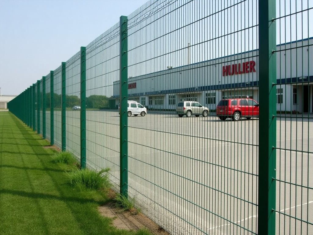
Sliding chain link fences combine the durability of woven steel mesh with a guided roller system that allows the panel to move horizontally along a track. This configuration is commonly specified for secure perimeters where space constraints prevent swing gates, such as loading docks, storage yards, and utility substations.
Product Overview
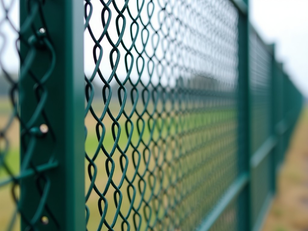
The sliding panel consists of a galvanized steel framework, a chain link fabric infill, and a set of precision‑mounted rollers that engage a C‑shaped or V‑shaped steel track. Panel widths typically range from 2.0 m to 6.0 m, with heights from 1.2 m to 3.0 m, and the system is designed to withstand wind loads up to 150 km/h when installed according to the manufacturer’s bracing guidelines.
Core Specifications
| Parameter | Typical Range | Notes |
|---|---|---|
| Panel Height | 1.2 m – 3.0 m | Custom heights available in 0.1 m increments |
| Panel Width (clear opening) | 2.0 m – 6.0 m | Multiple panels can be combined for larger openings |
| Mesh Opening (diamond) | 50 mm × 50 mm | Standard; 38 mm or 75 mm options on request |
| Wire Diameter | 2.0 mm – 3.5 mm (galvanized) | Thicker wire increases impact resistance |
| Roller Type | Sealed ball‑bearing, polyurethane‑coated | Low‑friction, maintenance‑free for 10 000 cycles |
| Track Material | Hot‑rolled steel, C‑profile, 2.5 mm thickness | Galvanized or powder‑coated finish |
| Wind Load Rating | Up to 150 km/h (with proper bracing) | Calculated per ASCE 7‑16 |
Material Options
- Galvanized steel wire (Z275 coating) – standard for corrosion resistance in outdoor environments.
- Stainless steel wire (Grade 304 or 316) – selected for coastal or chemical‑exposure sites where chloride resistance is required.
- PVC‑coated wire – provides a colored exterior (green, black, brown) and adds a barrier against direct water contact.
- Aluminum track – lighter alternative for installations where dead load on supporting structures must be minimized.
Customization Parameters
Beyond standard dimensions, the sliding chain link system can be adapted to meet specific project constraints. The following parameters are routinely adjusted during quotation:
- Track length and curvature – straight sections or custom‑bent radii to follow site contours.
- Roller spacing – typically every 400 mm to 600 mm along the panel edge; altered to accommodate higher load cases.
- Locking mechanisms – manual drop‑bolt, automatic latch, or electronic actuator integration.
- Bottom guide – rubber‑lined roller or steel shoe to prevent lateral drift.
- Surface finish – hot‑dip galvanizing, powder coating (RAL colors), or anodizing for aluminum tracks.
Typical Applications
Sliding chain link fences are chosen when a secure barrier must coexist with limited lateral space for gate swing. In manufacturing facilities, they protect conveyor aisles while allowing fork‑lift traffic to pass through a controlled opening. In utility substations, the see‑through mesh enables visual inspection of equipment while deterring unauthorized access. Agricultural operations use the system to divide large paddocks, where the sliding feature accommodates seasonal equipment movement without permanent gate installations.
Quality Assurance
Each production lot undergoes dimensional verification of wire diameter, mesh opening, and panel squareness using calibrated calipers and laser alignment tools. Roller assemblies are torque‑tested to confirm rolling resistance below 0.15 Nm per wheel. The finished panel is subjected to a 48‑hour salt‑spray test (ASTM B117) to validate coating adhesion, with acceptance criteria of less than 5 % red rust appearance. Documentation of these checks is provided with every shipment upon request.
Packaging and Logistics
- Panels are bundled in groups of up to four, wrapped in stretch film, and placed on pallets with corner protectors.
- Tracks and hardware are packed in sealed cardboard boxes with foam inserts to prevent deformation.
- Export shipments include ISPM‑15 compliant wooden pallets and moisture‑absorbent desiccant packs.
- Labeling contains part number, length, height, coating type, and QC reference for traceability.
Frequently Asked Questions
- Can dimensions be customized?
- Yes. Panel height, width, and mesh opening are adjusted per project drawings; custom track radii are also available.
- What information is required before quotation?
- Required inputs include clear opening size, desired height, wind load specifications, coating preference, and any required locking or automation accessories.
- What materials are available?
- Galvanized steel, stainless steel (304/316), PVC‑coated wire, and aluminum tracks are standard; specialty alloys can be sourced upon request.
- How is quality inspected?
- Incoming wire is checked for diameter and coating weight; mesh is verified for opening size; final assembly undergoes functional roll test and corrosion resistance verification.
- What packaging methods are available?
- Standard palletized stretch‑film wrapping; optional crate packaging for high‑value or hazardous‑area shipments.
- How are export shipments protected?
- Pallets are heat‑treated, wrapped in water‑resistant film, and secured with steel straps; corner boards prevent impact damage.
- What is the typical production lead time?
- Lead time ranges from 3 to 5 weeks for standard configurations; customized orders may extend to 6–8 weeks depending on material availability.
- How are samples arranged?
- Sample sections (typically 1 m × 1 m) can be shipped via express courier; costs are credited against a subsequent order.
Contact Us
For technical datasheets, CAD models, or a project‑specific quotation, please reach out to our sales engineering team. Provide the opening dimensions, height, and any special requirements such as coating or automation, and we will return a detailed response within one business day.