Factory Direct 3D Metal Mesh Fencing Manufacturer
Three‑dimensional metal mesh fencing consists of intersecting wires welded at nodes to form a rigid lattice with depth, providing both perimeter security and structural rigidity. Unlike traditional
Request a QuoteFactory Direct 3D Metal Mesh Fencing Manufacturer
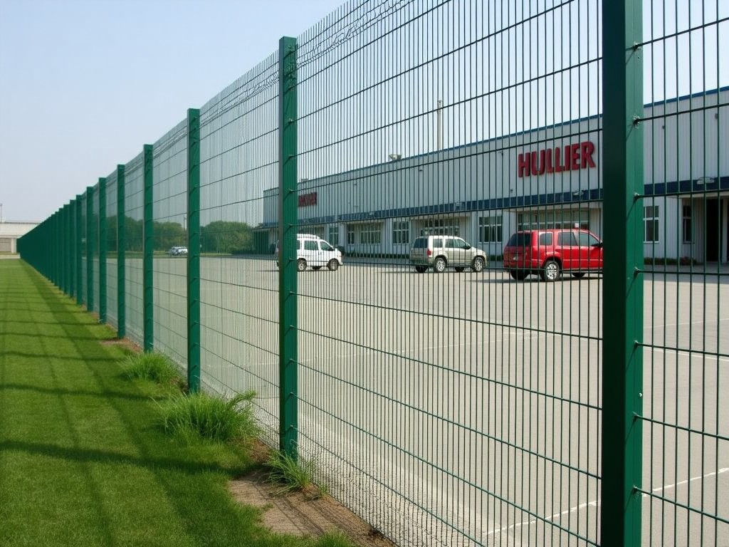
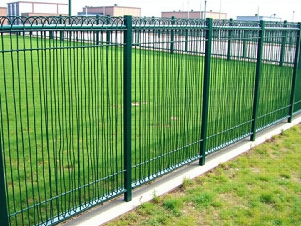
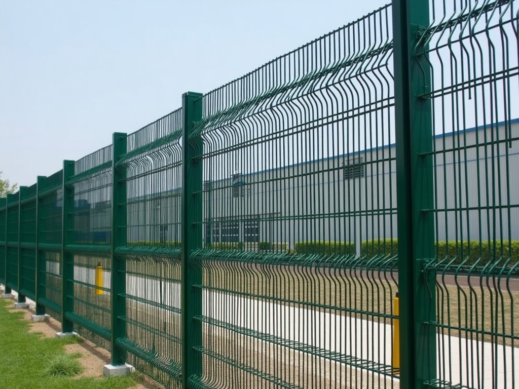
Three‑dimensional metal mesh fencing consists of intersecting wires welded at nodes to form a rigid lattice with depth, providing both perimeter security and structural rigidity. Unlike traditional 2D woven or chain‑link products, the 3D geometry distributes impact loads across multiple axes, reducing deformation under static and dynamic forces. This design is commonly selected for high‑traffic industrial sites, correctional facilities, and utility substations where both visibility and intrusion resistance are required.
Material Composition and Properties
The base wire is typically cold‑drawn low‑carbon steel with a tensile strength of 550 MPa and a yield strength of 350 MPa. For outdoor exposure, a hot‑dip zinc coating of 55 µm ± 5 µm (≈ 400 g/m²) is applied, meeting ISO 1461 standards. In environments with higher chloride or chemical loads, the same geometry can be produced from austenitic stainless steel grade 304 or 316, offering a pitting resistance equivalent number (PREN) above 25. These specifications allow designers to calculate deflection and load‑bearing capacity using standard beam theory on the welded node geometry.
Manufacturing Process
The process begins with drawing steel rod to the desired diameter (commonly 3.0 mm to 5.0 mm) while maintaining a tolerance of ±0.02 mm. Wires are then fed into a resistance‑spot welding station where opposing wires are fused at programmed intervals, creating a square or rectangular node pattern with a typical pitch of 50 mm × 50 mm. After welding, the mesh sheet is cut to length, flattened, and passed through a hot‑dip galvanizing line where immersion time and withdrawal speed control coating thickness. Final inspection includes visual node integrity checks and dimensional verification on a coordinate measuring machine.
Customization Options
- Wire diameter: 3.0 mm, 3.5 mm, 4.0 mm, 4.5 mm, or 5.0 mm, selected based on required load capacity.
- Mesh opening (pitch): 40 mm × 40 mm, 50 mm × 50 mm, 60 mm × 60 mm, or custom sizes to adjust visibility and climb resistance.
- Panel height: standard 1.2 m, 1.5 m, 1.8 m, 2.1 m, or cut to any length up to 6 m for seamless installation.
- Panel width: modular widths of 0.5 m, 1.0 m, 1.5 m, 2.0 m, enabling rapid on‑site assembly.
- Coating options: hot‑dip zinc (55 µm), zinc‑aluminum alloy (Zn‑Al 5 %), or powder‑coated polyester in RAL colors for aesthetic or additional corrosion protection.
- Post profiles: square steel tube 60 mm × 60 mm × 2.0 mm, round Ø48 mm × 2.5 mm, or C‑channel, all pre‑drilled for mesh attachment.
- Gate integration: single‑leaf, double‑leaf, or sliding gates with matching mesh infill and lock‑ready hardware.
Applications
In manufacturing and logistics campuses, the 3D mesh provides a clear line of sight for surveillance cameras while resisting vehicular impact; the welded nodes absorb energy from low‑speed collisions, reducing the need for frequent repairs compared to flexible chain‑link barriers.
Correctional facilities benefit from the small opening sizes and anti‑climb geometry; the 3D profile creates overlapping edges that hinder footholds, and the rigid lattice prevents deformation when subjected to sustained pressure or cutting attempts.
Utility substations require electromagnetic transparency; the non‑magnetic stainless‑steel option minimizes interference with nearby sensors, and the open mesh allows airflow for cooling transformers without compromising perimeter security.
Quality Control and Testing
Each coil of wire undergoes a diameter and tensile strength verification before welding; a sample of every 500 m of welded mesh is subjected to a peel test on the spot welds, requiring a minimum shear strength of 1.2 kN per node to pass. Coating thickness is measured with a magnetic‑induction gauge on five random points per panel, accepting only values within ±5 µm of the target. Final panels are checked for dimensional accuracy (±3 mm on height and width) and surface continuity using a 10× magnification lamp to detect missed welds or coating holidays.
Packaging and Shipping
Finished panels are stacked in bundles of five, separated by corrugated cardboard edge protectors to prevent abrasion during handling. Each bundle is wrapped in UV‑stabilized stretch film and secured to a standard 1.1 m × 1.1 m pallet with polyester strapping. For export, pallets are placed in 20‑foot or 40‑foot containers with moisture‑absorbent desiccant bags and subjected to ISPM‑15 compliant heat‑treated wood pallets to meet international phytosanitary requirements.
Technical Specifications
| Parameter | Typical Value | Notes / Customization |
|---|---|---|
| Wire Diameter | 3.0 mm – 5.0 mm | Selected per load requirement; tolerance ±0.02 mm |
| Tensile Strength (wire) | ≈ 550 MPa | Cold‑drawn low‑carbon steel; higher grades available |
| Yield Strength (wire) | ≈ 350 MPa | Ensures elastic recovery under service loads |
| Mesh Pitch (opening) | 40 mm × 40 mm to 60 mm × 60 mm | Custom pitches available for specific visibility or climb resistance |
| Panel Height | 1.2 m – 2.1 m (standard) | Cut‑to‑length up to 6 m for seamless runs |
| Panel Width (module) | 0.5 m – 2.0 m | Enables rapid on‑site assembly |
| Coating Thickness (Zn) | 55 µm ± 5 µm (≈ 400 g/m²) | Hot‑dip galvanizing; Zn‑Al or powder coat options |
| Salt Spray Resistance (Zn) | ≥ 500 h (ISO 9227) | Stainless‑steel grades exceed 1500 h |
| Maximum Post Spacing | 3.0 m | Based on 50 mm × 50 mm mesh and standard wind load |
| Wind Load Resistance | Up to 150 km/h gust | Calculated per ASCE 7‑16 for typical panel size |
Frequently Asked Questions
Can dimensions be customized? Yes. Wire diameter, mesh pitch, panel height and width, and post spacing are all adjustable to meet project‑specific load and clearance requirements.
What information is required before quotation? We need the desired wire diameter, mesh opening, panel dimensions, coating type, post specification, and any special requirements such as gate integration or corrosion‑resistance grade.
How is quality inspected? Each production lot undergoes wire tensile testing, weld shear strength verification, coating thickness measurement, and final dimensional audit before packaging.
What packaging methods are available? Standard packaging includes corrugated edge protectors, UV‑stabilized stretch film, and palletizing with polyester strapping; custom crating or container‑specific solutions can be arranged upon request.
What is the typical production lead time? Lead times range from 2 to 4 weeks depending on order complexity, coating selection, and current production load.