Custom Metal Wire Fence Panels
This page explains the engineering basis for specifying custom‑fabricated wire fence panels, covering material selection, dimensional options, mechanical performance, and typical industrial uses. The
Request a QuoteCustom Metal Wire Fence Panels
This page explains the engineering basis for specifying custom‑fabricated wire fence panels, covering material selection, dimensional options, mechanical performance, and typical industrial uses. The information is intended to help procurement engineers evaluate suitability without relying on generic marketing claims.
Overview of Wire Fence Panel Construction
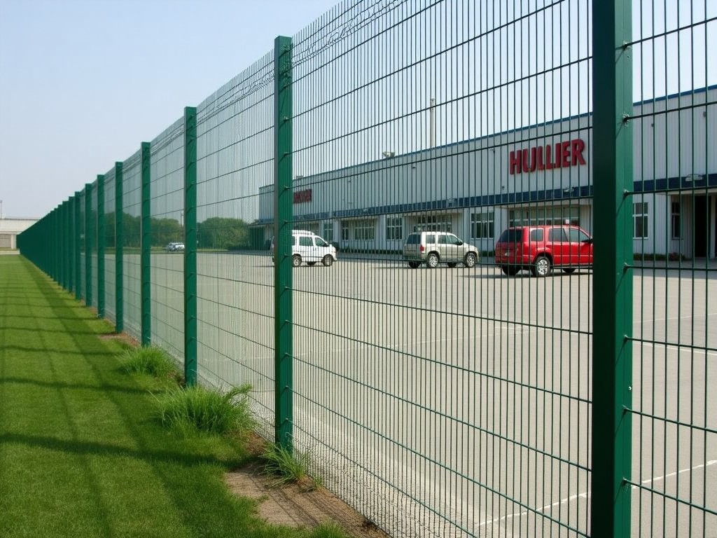
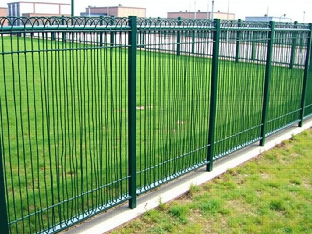
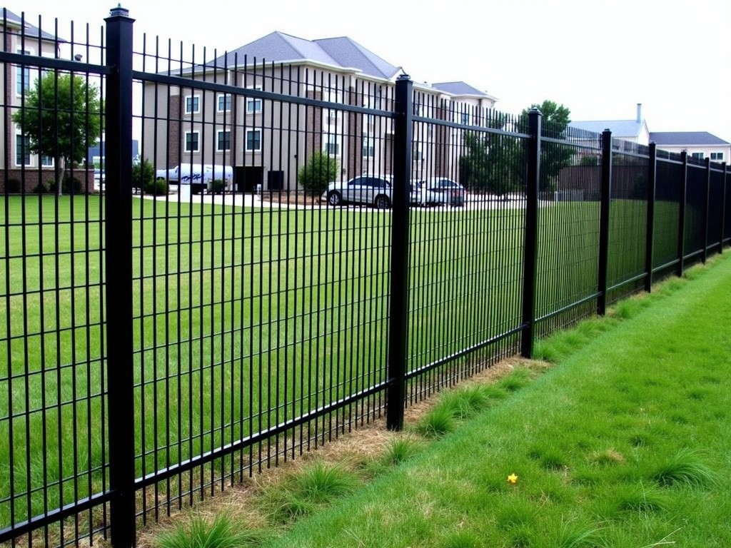
A wire fence panel consists of longitudinal and transverse wires welded or woven at intersections to form a rectangular mesh. The panel is then framed with peripheral members—typically angle or tube sections—to provide edge rigidity and facilitate handling. Panel depth (wire diameter) and opening size directly influence stiffness, impact resistance, and visibility.
Design variables include wire gauge (often expressed as AWG or mm), mesh opening (clear spacing between wires), frame profile dimensions, and surface treatment. Each variable can be adjusted independently to meet load, corrosion, and aesthetic requirements.
Material Options and Typical Values
Selecting the base wire material determines corrosion resistance, tensile strength, and weldability. Common choices are low‑carbon steel, galvanized steel, stainless steel (grades 304 or 316), and aluminum alloy. Coatings such as hot‑dip galvanizing, PVC powder coating, or epoxy can be added to extend service life in aggressive environments.
| Parameter | Typical Range / Options | Notes |
|---|---|---|
| Wire material | Low‑carbon steel, Galvanized steel, SS 304, SS 316, Al‑Mg alloy | Selection based on environment and load |
| Wire diameter (AWG) | 8 – 16 AWG (≈ 2.6 – 1.3 mm) | Thicker wire increases panel moment of inertia |
| Mesh opening (clear) | 25 mm – 100 mm square or rectangular | Smaller openings improve containment but raise wind load |
| Frame profile | Angle 25×25×3 mm, Tube 32×32×2 mm, Custom | Provides edge stiffening and mounting points |
| Surface treatment | Hot‑dip galvanizing (≈ 55 µm Zn), PVC coating (≈ 0.2 mm), Epoxy primer + topcoat | Chosen per corrosion class (C1‑C5) |
Design & Customization Logic
Customization begins with defining the design load case—wind pressure, impact load, or animal containment force. Using simple beam theory, the required wire diameter can be estimated from the bending stress formula σ = M·c/I, where M is the moment from the applied load, c is half the wire diameter, and I is the second moment of area of the wire cross‑section.
Mesh opening influences the effective solidity ratio (area of wire / total panel area). A lower solidity reduces wind drag but may decrease resistance to small‑object penetration. Designers often iterate between opening size and wire gauge to achieve a target solidity between 0.15 and 0.30 for typical perimeter security panels.
Frame selection follows from the required panel stiffness and mounting method. Angle frames provide easy welding or bolting to posts, while tubular frames allow for slip‑over connections and reduced protrusion. Frame depth is usually chosen to be at least 1.5 × the wire diameter to avoid local buckling under transverse loads.
Typical Industrial Applications
In manufacturing facilities, wire fence panels serve as machine guarding where visibility and airflow are required. The open mesh allows operators to see moving parts while preventing contact with hazardous zones. Panels are sized to meet ISO 14120 guarding standards, with opening limits based on reach‑through distances.
Agricultural installations use panels for livestock containment and predator exclusion. Here, the key parameters are wire diameter sufficient to resist animal impact and opening size small enough to prevent hoof or head passage. Galvanized or PVC‑coated finishes are common to withstand outdoor exposure and occasional chemical spray from fertilizers.
Infrastructure projects such as highway medians or airport perimeters employ panels as anti‑climb barriers. The design emphasizes high tensile wire, small openings (< 40 mm), and a robust frame to resist dynamic loads from vehicles or attempted breaches. Corrosion class C4‑C5 coatings are specified for coastal or de‑icing salt environments.
Quality Assurance and Testing Philosophy
Reliability is built into the manufacturing process through material traceability, weld integrity checks, and dimensional verification. Each wire lot is accompanied by a mill certificate confirming chemical composition and mechanical properties. Weld points are inspected visually and, for critical applications, by nondestructive ultrasonic testing to detect lack of fusion or porosity.
Finished panels undergo a dimensional audit: wire diameter, opening size, frame squareness, and overall length/width tolerances (typically ± 2 mm). Coating thickness is measured with a magnetic induction or eddy‑current gauge to confirm compliance with the agreed micron range. These checks are documented in a lot‑specific test report supplied with each shipment.
Installation Considerations
Panels are designed for straightforward handling; typical unit weights range from 8 kg/m² for light‑gauge aluminum to 25 kg/m² for heavy‑gauge galvanized steel. Lifting points are integrated into the frame (e.g., pre‑drilled holes or lifting lugs) to facilitate crane or forklift placement.
Mounting methods include bolt‑through flange plates, welded brackets, or slip‑over post caps. The choice depends on required permanence, allowable on‑site welding, and expected maintenance frequency. Proper tensioning of the mesh is not required because the frame carries the load; however, panels should be installed flat to avoid premature stress concentrations.
Frequently Asked Questions
- Can dimensions be fully customized? Yes—wire gauge, mesh opening, frame profile, panel length, and height are all specified per project drawing.
- What information is needed for a quotation? Required inputs include design load (wind pressure or impact), environmental corrosivity class, desired finish, overall dimensions, and any special mounting features.
- Which materials are available for corrosive environments? Stainless steel grades 304/316, hot‑dip galvanized steel with ≥ 55 µm Zn, and PVC‑coated steel are standard options; aluminum is available where weight is critical.
- How is weld quality verified? Visual inspection per ISO 5817 is performed on 100 % of welds; ultrasonic spot testing is offered for high‑risk applications.
- What packaging methods protect panels during transit? Panels are stacked on pallets with corner protectors, wrapped in stretch film, and sealed in weather‑resistant crate or cardboard sleeves as required.
- What is the typical lead time? Standard lead time is 3‑4 weeks after drawing approval; expedited options are available upon request.
Request Technical Details
To discuss a custom wire fence panel solution for your facility, provide the project specifications outlined above. Our engineering team will review the load case, material suitability, and fabrication constraints before issuing a detailed quote and lead‑time confirmation.