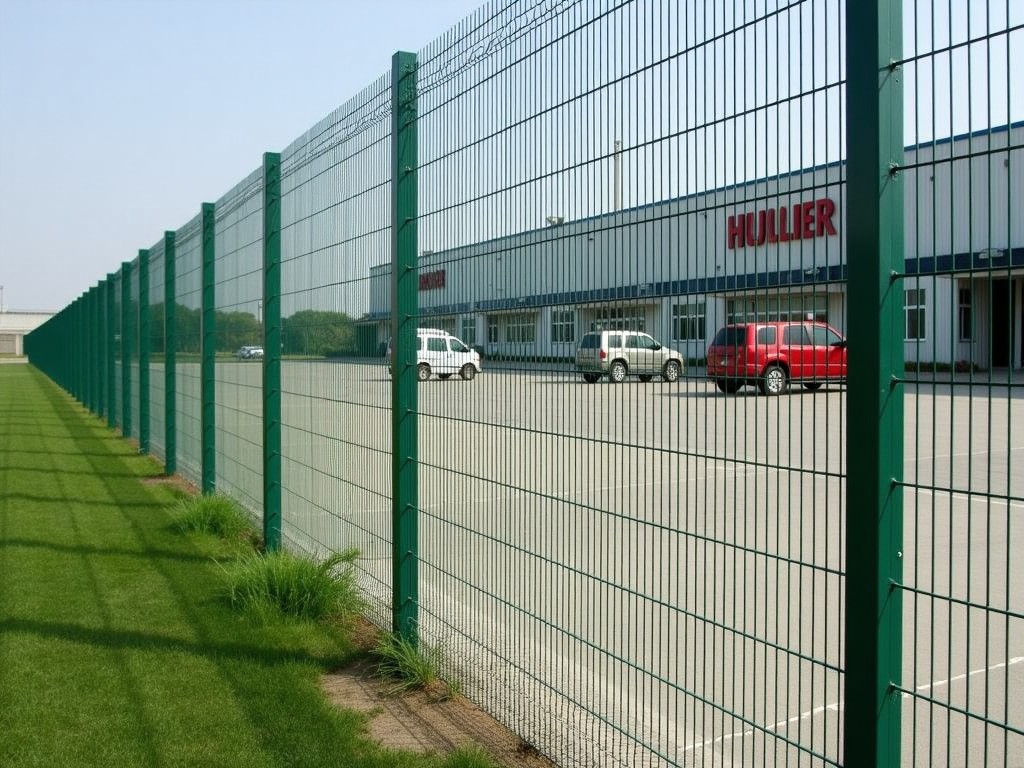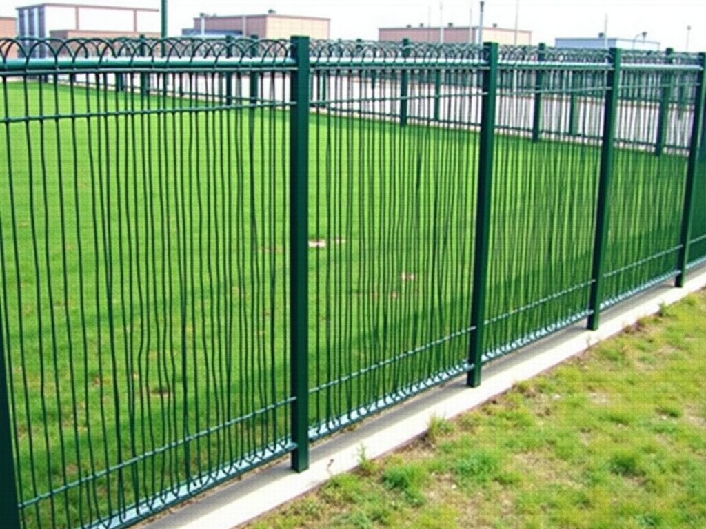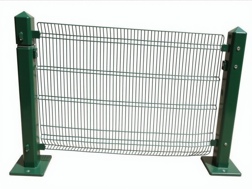
Custom Metal Crowd Control Barrier Fencing Manufacturer
Crowd control barriers must absorb impact forces from moving groups, resist wind pressure on temporary installations, and allow fast assembly without specialized tools. The design process begins by
Request a QuoteCustom Metal Crowd Control Barrier Fencing Manufacturer
Crowd control barriers must absorb impact forces from moving groups, resist wind pressure on temporary installations, and allow fast assembly without specialized tools. The design process begins by defining the required load cases, environmental conditions, and handling constraints that shape material choices, joint geometry, and overall dimensions.
Material Selection and Structural Properties
Structural members are typically produced from hot‑rolled steel grades S235JR (yield ≈235 MPa) or S355J2 (yield ≈355 MPa), selected based on the anticipated dynamic load and welding requirements. Corrosion protection is achieved through hot‑dip galvanizing, delivering a zinc coating of roughly 80 µm thickness, which provides a maintenance‑free service life exceeding 15 years in temperate atmospheres. For environments with high chloride exposure or strict aesthetic specifications, alternatives include stainless steel grade 304 or a powder‑coated polyester finish (≈60 µm) applied over the galvanized layer.
- S235JR – good formability, moderate strength, cost‑effective for low‑impact zones.
- S355J2 – higher strength‑to‑weight ratio, suitable for high‑load or wind‑exposed layouts.
- Hot‑dip galvanized coating – 70‑90 µm typical, uniform coverage, sacrificial protection.
- Powder‑coat over galvanize – additional UV stability, colour options, 50‑70 µm film.
- Stainless steel 304 – passive chromium oxide layer, resistant to pitting in marine settings.
Key Design Parameters
| Parameter | Typical Value | Customizable Range |
|---|---|---|
| Panel width (clear opening) | 2.0 m | 1.5 m – 3.0 m (modular increments) |
| Panel height | 1.1 m | 0.9 m – 1.5 m (subject to stability checks) |
| Post spacing (center‑to‑center) | 2.0 m | 1.5 m – 2.5 m (adjusted for load) |
| Interlocking pin diameter | 20 mm | 16 mm – 25 mm (high‑shear applications) |
| Design wind load (basic) | 0.6 kN/m² | Up to 1.2 kN/m² with reinforced posts |
| Impact resistance (dynamic) | 5 kN per post (equivalent to 500 kg at 2 m/s) | Up to 8 kN with larger sections |
Values above represent common configurations; final specifications are derived from project‑specific load calculations, site wind maps, and anticipated crowd densities.
Customization Options
- Variable panel lengths to match site layouts without cutting on‑site.
- Alternative connection systems: pin‑and‑socket, bolt‑flange, or quick‑release clamps.
- Integrated signage brackets or LED strip mounts for night‑time visibility.
- Base plates with adjustable feet for uneven surfaces or temporary ballast.
- Colour coding via powder coat to aid crowd flow direction.
Typical Applications and Functional Fit
In transportation terminals, barriers channel passenger queues while resisting the lateral forces generated by moving luggage carts and occasional surge flows. The modular width of 2 m allows a single operator to position a segment in under 30 seconds, reducing labor costs during peak periods.
Construction sites utilize the same system to delineate hazardous zones; the hot‑dip galvanized finish withstands splashes of concrete slurry and prolonged UV exposure without degradation, maintaining structural integrity for the duration of the project.
Public events such as concerts or sports matches require rapid deployment and removal; the interlocking pin design provides a shear capacity of 5 kN per joint, sufficient to withstand dynamic loads from crowd sway while allowing disengagement with a standard lifting tool.
Manufacturing Process and Quality Assurance
Production starts with CNC‑cut blanks to nominal dimensions, followed by robotic welding of stiffeners and connection lugs. Weld penetrations are inspected via ultrasonic testing to confirm a minimum throat thickness of 0.7 × parent material thickness. After welding, assemblies undergo a pre‑treatment bath (alkaline degreasing, zinc phosphate) before hot‑dip galvanizing in a zinc bath maintained at 450 ± 5 °C. Coating thickness is measured with a magnetic induction gauge at five points per panel; acceptance criteria follow ISO 1461 (≥55 µm average, ≤15 % variation). Final inspection includes dimensional verification (±2 mm on length, ±1 mm on height) and functional load testing of a sample joint to 1.5 times the design load.
Packaging and Logistics
Finished barriers are stacked on pallets with protective corner guards and stretch‑wrapped to prevent surface abrasion. Each pallet holds up to 10 panels (total weight ≈1.2 tonnes) and is secured with steel strapping. For overseas shipments, panels are placed in weather‑proof crates with internal bracing to resist shock and vibration during transit, complying with ISPM‑15 wood packaging standards.
Frequently Asked Questions
A: Height is fixed by the panel geometry; however, modular extensions can be added atop existing units using compatible spacer posts if local regulations require a taller configuration.
A: Project layout (plan view with required lengths), anticipated load cases (crowd density, wind zone), desired finish (galvanized, powder coat, stainless), and any special mounting accessories (signage, lighting).
A: Hot‑dip galvanized steel is standard; for marine or chemical exposure, stainless steel grade 304 or a duplex grade can be supplied upon request.
A: Each interlocking pin assembly undergoes a tensile test to 1.2 times the rated shear load, and a random sample of finished panels is subjected to a cyclic load test (10 000 cycles) to confirm fatigue performance.
Next Steps
To discuss a tailored barrier solution for your facility, provide the project details outlined above. Our engineering team will return a detailed proposal, including CAD layout, material certification, and estimated lead time.