Factory Direct Drain Channel Steel Grating Factory
Drain channel steel grating combines a load‑bearing grating surface with an integrated channel that directs runoff to drainage points. This configuration reduces ponding on flat industrial floors
Request a QuoteFactory Direct Drain Channel Steel Grating
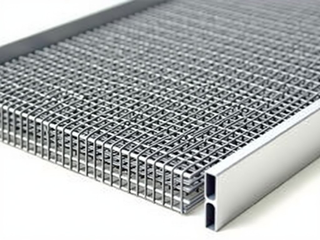
Drain channel steel grating combines a load‑bearing grating surface with an integrated channel that directs runoff to drainage points. This configuration reduces ponding on flat industrial floors while providing a walkable or driveable surface. The grating consists of longitudinal bearing bars intersected by transverse cross bars, forming a rigid open‑area matrix.
Material Selection and Mechanical Properties
Standard grating is produced from hot‑rolled carbon steel grades such as Q235 or Q345, with yield strengths ranging from 235 MPa to 345 MPa. Bearing bar thickness typically varies from 3 mm to 12 mm, and bar height from 20 mm to 50 mm, allowing designers to match the grating to expected live loads. Surface treatments include hot‑dip galvanizing (minimum 60 µm zinc coating) or epoxy powder coating for corrosive environments.
Structural Design of Drain Channel Grating
The channel is formed by bending the grating panel into a U‑shape with a nominal depth of 50 mm to 150 mm, creating a concealed conduit for water. Load is transferred from the bearing bars to the channel walls, which act as stiffeners that increase the section modulus. Finite‑element analysis shows that a 75 mm deep channel with 6 mm bearing bars can sustain a uniformly distributed load of 15 kN/m² with deflection under 5 mm.
Hydraulic Performance and Drainage Efficiency
Open area ratio, defined as the net void area divided by total grating area, typically ranges from 25 % to 45 % depending on bar spacing. A 30 % open area with 25 mm bar spacing yields a hydraulic conductivity comparable to a smooth pipe of equivalent diameter, facilitating flow rates of up to 0.8 L/s per metre of channel width under a 1 % slope. Manning’s roughness coefficient for the grating surface is approximately 0.015, similar to that of polished concrete.
Typical Applications in Industrial Facilities
In food‑processing plants, the grating’s smooth, easy‑to‑clean surface prevents product accumulation while the channel captures wash‑down water, reducing slip hazards. Chemical facilities benefit from the corrosion‑resistant coating, which protects against splashes of acids and alkalis. Power‑generation stations install drain channel grating beneath turbine foundations to manage cooling‑water runoff without compromising access for maintenance equipment.
Quality Assurance and Testing Procedures
Each batch undergoes dimensional inspection using laser scanners to verify bar spacing, channel depth, and overall length within ±0.5 mm tolerance. Welded joints are subjected to tensile shear testing, with a minimum acceptable strength of 80 % of the parent metal’s yield strength. Load‑deflection tests are performed on a representative sample, applying a gradual increase to 1.5 times the design load and recording residual deformation.
Customization Options
Customers can specify bearing bar dimensions, channel depth, and overall panel length to match site constraints. Surface finish options include hot‑dip galvanizing, thermal spray aluminum, or a two‑coat epoxy system. Additional features such as anti‑slip serrations, integrated litter baskets, or removable access covers can be incorporated during fabrication.
Technical Specifications
| Parameter | Typical Value | Customizable Range |
|---|---|---|
| Bearing bar thickness | 6 mm | 3 mm – 12 mm |
| Bearing bar height | 30 mm | 20 mm – 50 mm |
| Channel depth | 75 mm | 50 mm – 150 mm |
| Open area ratio | 30 % | 20 % – 45 % |
| Design load (UDL) | 15 kN/m² | 5 kN/m² – 30 kN/m² |
| Surface coating | Hot‑dip galvanizing (60 µm) | Galvanizing, epoxy, thermal spray Al |
| Maximum panel length | 6 m | Up to 12 m with splices |
Frequently Asked Questions
- Q: Can dimensions be customized to fit existing trench layouts? A: Yes, bearing bar size, channel depth, and panel length are adjusted per project drawings; custom lengths up to 12 m are achievable with spliced sections.
- Q: What information is required before a quotation can be issued? A: Required data include intended load rating, channel dimensions, bar spacing, surface finish preference, and any special features such as anti‑slip treatment.
- Q: Which materials are available for corrosive environments? A: Hot‑dip galvanized carbon steel, epoxy‑coated steel, and thermal‑spray aluminum are standard options; stainless steel grades are offered upon request.
- Q: How is quality inspected before shipment? A: Inspection includes dimensional verification, weld strength testing, coating thickness measurement, and load‑deflection validation per ISO 12944‑5.
- Q: What packaging methods protect the grating during export? A: Panels are bundled with steel straps, placed on pallets, and covered with waterproof shrink film; corner protectors prevent impact damage.
- Q: What is the typical production lead time? A: Lead time ranges from 2 to 4 weeks depending on order complexity and current factory capacity.
- Q: How are samples arranged for evaluation? A: Sample sections (typically 0.5 m × 0.5 m) can be shipped at the buyer’s expense; freight charges are credited against the final order value.