Custom Steel Mesh Walkway Panels Manufacturer
Walkway panels fabricated from welded steel mesh provide a slip‑resistant, load‑bearing surface for industrial platforms, mezzanines, and maintenance aisles. The open‑grid design allows drainage,
Request a QuoteCustom Steel Mesh Walkway Panels
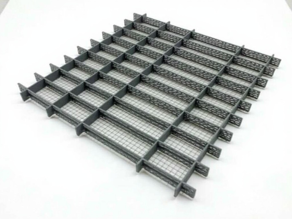
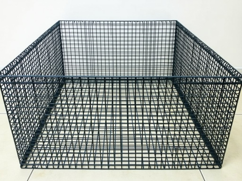
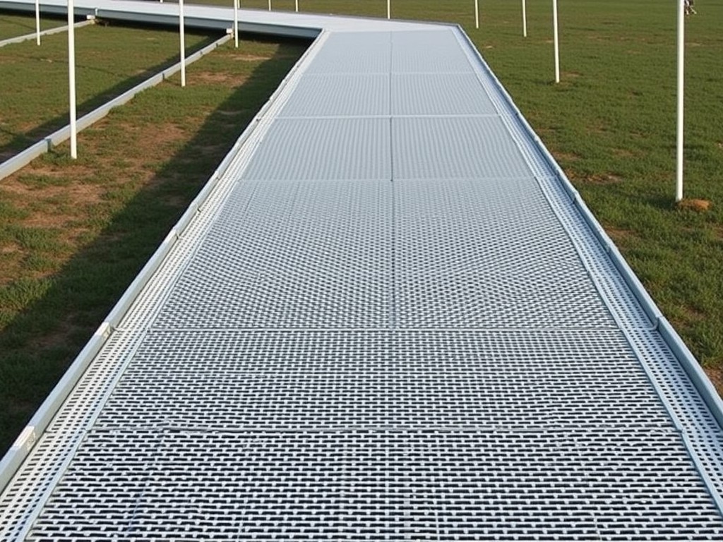
Walkway panels fabricated from welded steel mesh provide a slip‑resistant, load‑bearing surface for industrial platforms, mezzanines, and maintenance aisles. The open‑grid design allows drainage, ventilation, and easy integration with handrails or toe‑guards while maintaining a high strength‑to‑weight ratio.
Material Options and Mechanical Properties
Base material is typically hot‑rolled carbon steel conforming to ASTM A36, with yield strength around 250 MPa and tensile strength 400‑550 MPa. For corrosive environments, panels can be supplied in galvanized (zinc coating ≥ 60 g/m²) or stainless steel grades 304/316, offering corrosion resistance suitable for chemical processing or marine applications.
Mesh opening sizes range from 20 mm × 20 mm to 50 mm × 50 mm, with wire diameters from 3 mm to 6 mm selected based on required load capacity and deflection limits. Panel thickness (overall height) is usually 25 mm to 50 mm, providing sufficient rigidity for spans up to 2.4 m without intermediate support when properly fastened.
Design Flexibility and Customization
Panels are cut to length and width per project drawings, with standard tolerances of ± 2 mm on dimensions and ± 1 mm on squareness. Custom features include integrated mounting flanges, pre‑drilled bolt holes, or edge reinforcement bars welded to the perimeter for increased shear capacity.
Surface treatments beyond galvanizing are available, such as powder coating in RAL colors for aesthetic matching or anti‑static finishes for electronics facilities. All customizations are documented in the fabrication drawing package and reviewed before production.
Manufacturing Process Overview
Raw steel coils are slit to the specified wire diameter, then drawn and welded into mesh using automated resistance spot welders that ensure consistent weld strength (≥ 90 % of base metal tensile). The welded mesh is flattened, cut to panel size, and any secondary operations such as hole punching or flange forming are performed on CNC presses.
After fabrication, panels undergo cleaning (alkaline degreasing) before coating. Galvanizing follows the hot‑dip process per ISO 1461, while powder coating involves electrostatic application and curing at 180‑200 °C for 10‑15 minutes. Each step is logged for traceability.
Quality Control and Testing
Dimensional verification is performed on every batch using calibrated calipers and coordinate‑measuring machines, with acceptance criteria based on the project‑specific tolerance table. Visual inspection checks for weld continuity, coating uniformity, and absence of sharp edges.
Mechanical proof tests include a point load test at the panel centre, measuring deflection; allowable deflection is limited to span/200 per typical walkway design standards. Coating thickness is measured with a magnetic gauge, ensuring galvanized layers meet the required µm thickness.
Typical Applications
- Industrial mezzanine floors where lightweight yet sturdy walking surfaces are required.
- Maintenance walkways around machinery, allowing drainage of oils and coolants.
- Stair treads and landing platforms in power plants or refineries, providing slip resistance.
- Cleanroom corridors where perforated surfaces reduce particle accumulation.
- Outdoor pedestrian ways in marine environments, utilizing stainless steel grades for corrosion resistance.
Technical Data
| Property | Typical Value | Unit |
|---|---|---|
| Yield Strength (Base Steel) | 250 | MPa |
| Tensile Strength (Base Steel) | 450 | MPa |
| Mesh Opening Size | 20‑50 | mm |
| Wire Diameter | 3‑6 | mm |
| Panel Height (Overall) | 25‑50 | mm |
| Maximum Recommended Span (No Intermediate Support) | 2.4 | m |
| Galvanized Coating Thickness | ≥ 60 | g/m² |
Frequently Asked Questions
- Can panel dimensions be customized to fit irregular layouts?
- What information is required for a quotation?
- Which material grades are available for corrosive environments?
- How is product quality verified before shipment?
- What packaging methods protect panels during transit?
- What is the typical production lead time?
Yes, panels are cut to length and width per supplied drawings, with standard tolerances of ± 2 mm.
Required data includes overall dimensions, mesh opening, wire diameter, material grade, coating preference, and any special features such as mounting holes or flanges.
Hot‑dip galvanized carbon steel, stainless steel 304, and stainless steel 316 are standard options; alternative alloys can be quoted upon request.
Each lot undergoes dimensional inspection, visual weld and coating review, and mechanical proof testing per project specifications; test reports are available with documentation.
Panels are stacked on pallets, separated by corrosion‑interleaving paper, and secured with stretch wrap or steel straps; export shipments include additional edge protection and moisture‑barrier lining.
Lead time ranges from 2‑4 weeks depending on order complexity and current shop load; expedited schedules are available for critical projects.
Ready to Discuss Your Project?
Provide your layout sketches, load requirements, and environmental conditions to receive a detailed technical proposal and lead‑time estimate.
Request a Quote